Offshore wind operators are under growing pressure to cut diesel consumption across crew transfer and service
operation fleets, while charterers increasingly specify electric or hybrid propulsion as a tender requirement. Turbine-based and foundation-based charging infrastructure is now being installed across operating wind farms, giving CTVs and SOVs the opportunity to recharge during standby and transfer windows rather than returning to port.
For many operators, the commercial drivers are now converging: charterer decarbonisation clauses, extended range
requirements for electric and hybrid vessels, reduced fuel logistics, and improved crew transfer availability during
weather windows. Offshore charging integration is increasingly evaluated alongside hybrid and BESS integration, DP2 conversion, and wider electrical modernisation programmes, making it one of the fastest-emerging retrofit categories across offshore wind support fleets.
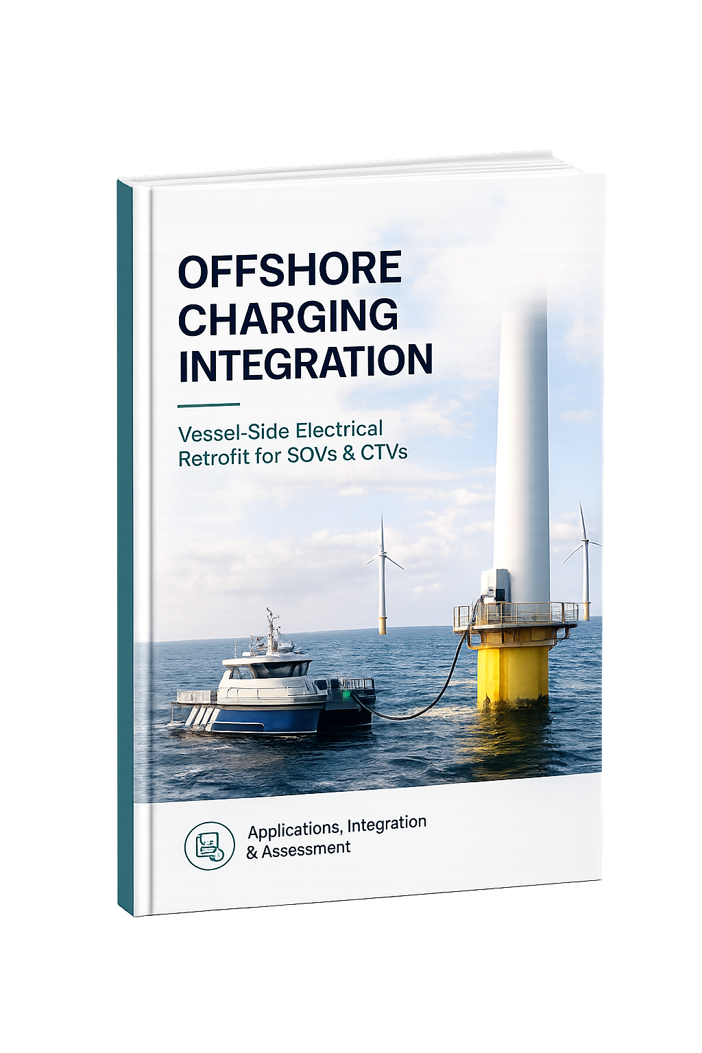
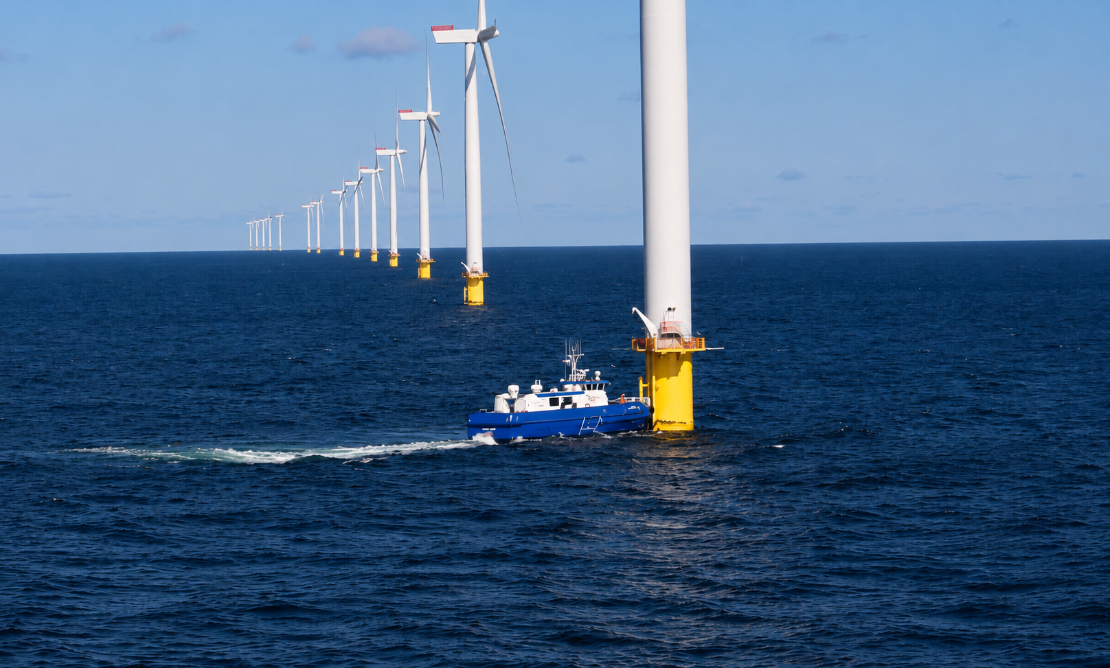
Offshore charging integration connects a vessel to power generated at the wind turbine, foundation, substation, or a dedicated charging buoy, using an automated connector that docks into a receptacle fitted on the vessel. Once connected, the vessel holds an economical station-keeping position — typically reduced-thruster DP or push-on mode — for the duration of the charge cycle.
In practical terms, the vessel must be technically ready to receive, manage, and store that power safely and reliably.
This primarily affects:
Offshore charging capability is becoming an operational expectation in wind farm O&M tenders, as charterers move toward electric and hybrid fleet requirements. For CTV operators, mid-shift recharging extends operating range and reduces reliance on port-based charging — making vessel-side readiness a deciding factor in long-term contract flexibility, alongside Class compliance.
A complete offshore charging retrofit involves significantly more than fitting a receptacle. Safe integration ties
together electrical engineering, DP and positioning control, automation, protection philosophy, and Class approval
within the vessel's existing architecture.
The receptacle ("catcher") forms the vessel interface with the structure-side connector ("reeler"). Depending on
vessel layout, it may be integrated on deck, in a dedicated recess, or on a fendered approach face.
Typical considerations include:
• connector alignment tolerance and mechanical mating
• IP protection and subsea-rated sealing
• mounting location and crew access
• mechanical protection and fendering
• Class approval requirements
DP or positioning-control integration is required to hold the vessel within connection tolerance for the duration of the
charge cycle, whether under reduced-thruster DP or push-on mode against the structure.
Integration typically covers:
• economical station-keeping mode logic
• connection-tolerance monitoring and alarms
• interface between DP/joystick control and the charge-connection sequence
• fallback and safe-disconnect procedures on position loss
Onboard battery sizing determines how much charge the vessel can accept per connection and how that energy is
used across transit, DP, and standby.
Sizing depends on:
• vessel operational profile and shift pattern
• charge rate accepted from the offshore charging point
• available installation space and thermal management
• redundancy and safety philosophy
Integrating a new charging inlet typically requires modification of the existing switchboard architecture.
Scope commonly includes:
• charging inlet feeder integration
• protection relay coordination
• discrimination studies
• load transfer sequencing between charge and propulsion/DP loads
• short-circuit verification
Power Management System integration is essential for safe, repeatable charging operations.
PMS modifications usually include:
• charge acceptance and handshake logic with the offshore charging system
• battery state-of-charge monitoring and charge-rate control
• controlled transfer between charging and DP/propulsion modes
• alarm and monitoring integration
One of the most technically sensitive aspects of offshore charging integration is the electrical interface between the
vessel and the structure-side charging point, including galvanic isolation, fault current behaviour, and emergency
disconnect logic.
Protection engineering typically includes evaluation of galvanic isolation requirements, earthing continuity, safety
interlocks, emergency quick-disconnect systems, and relay coordination settings, remaining fully compliant with Class
requirements throughout connection, charging, and disconnection sequences.
Electric and hybrid CTVs, SOVs, and CSOVs operating on offshore wind farms typically show the strongest operational case, particularly where turbine or foundation-mounted charging infrastructure is already installed or planned.
Not always. Smaller CTVs can connect using a push-on approach against the structure, while SOVs and larger vessels typically rely on DP-assisted station-keeping. DP2 is not a strict prerequisite, but it is increasingly specified for wind farm charter access generally.
Offshore charging integration draws on Class society guidance for battery and shore-power readiness — including DNV's "Battery ready" and "Shore power ready" notations — alongside vessel-specific electrical and DP class requirements.
Yes. Most offshore charging projects are engineered together with battery sizing and hybrid integration, since the onboard BESS is what actually stores and uses the charge.
Not always. Some receptacle and cabling work can be completed afloat, though many owners coordinate charging integration with a scheduled drydock alongside DP2, hybrid, or switchboard upgrades.


