 Request an assessment
 +40790870949
Generators are typically oversized for worst-case conditions but spend most of their service life running at partial load. In a fixed-speed installation, excess flow is controlled through throttling valves or dampers — the motor continues drawing full power regardless of actual demand, burning fuel for work never delivered.
A marine VFD retrofit eliminates this waste at the source. By varying motor speed to match real-time demand rather than restricting flow after the fact, energy consumption drops dramatically, halving speed alone reduces power draw by up to 87.5%. The same principle applies to seawater cooling pumps, ballast pumps, HVAC fans, bilge pumps, and compressors across any vessel class.
GLO Marine's marine VFD retrofit solutions upgrade existing fixed-speed systems with minimal off-hire time, full class society approval, and measurable reductions in auxiliary engine load, supporting IMO CII, EEXI compliance, and fleet decarbonisation targets.
Traditional marine generators run at a constant speed regardless of actual power demand. This means your vessel burns the same fuel at anchor as it does at full sea speed — a fundamental inefficiency that compounds across every hour of operation, every voyage, every year.
For vessel operators facing rising bunker fuel costs, increasingly stringent IMO emissions regulations, and competitive pressure on operating margins, fixed-speed generator systems are no longer viable.
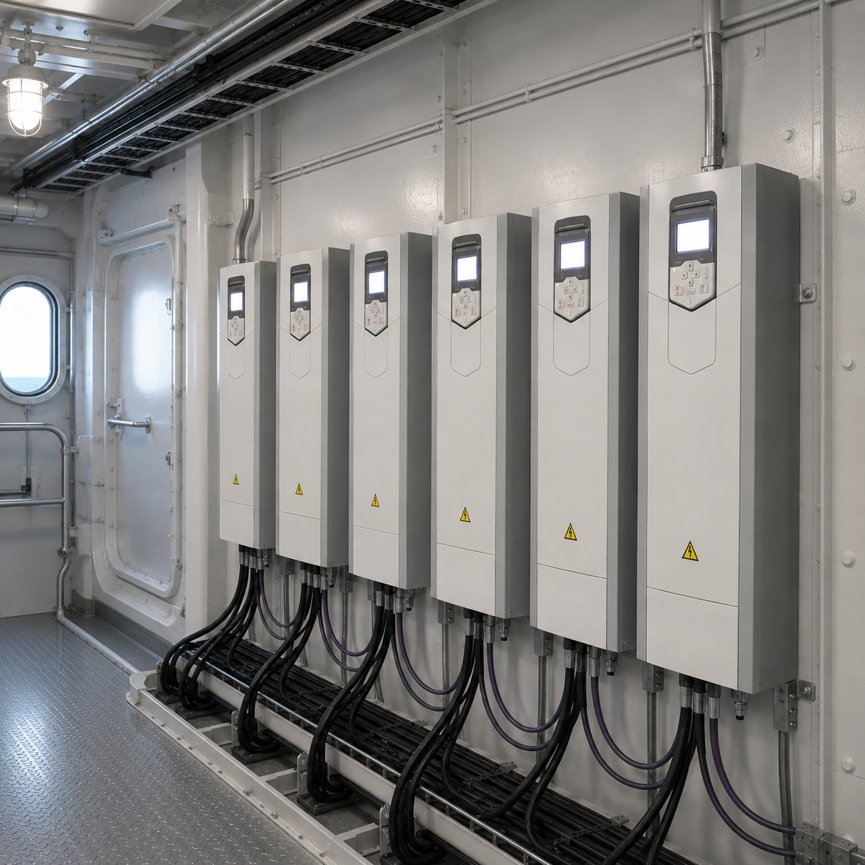
A Variable Frequency Drive (VFD), also called a variable speed drive (VSD) or marine inverter drive, is an advanced power electronics system that controls the rotational speed and torque of an electric motor or generator by varying the frequency and voltage of its electrical supply. These systems are typically integrated as part of a complete marine VFD system architecture.
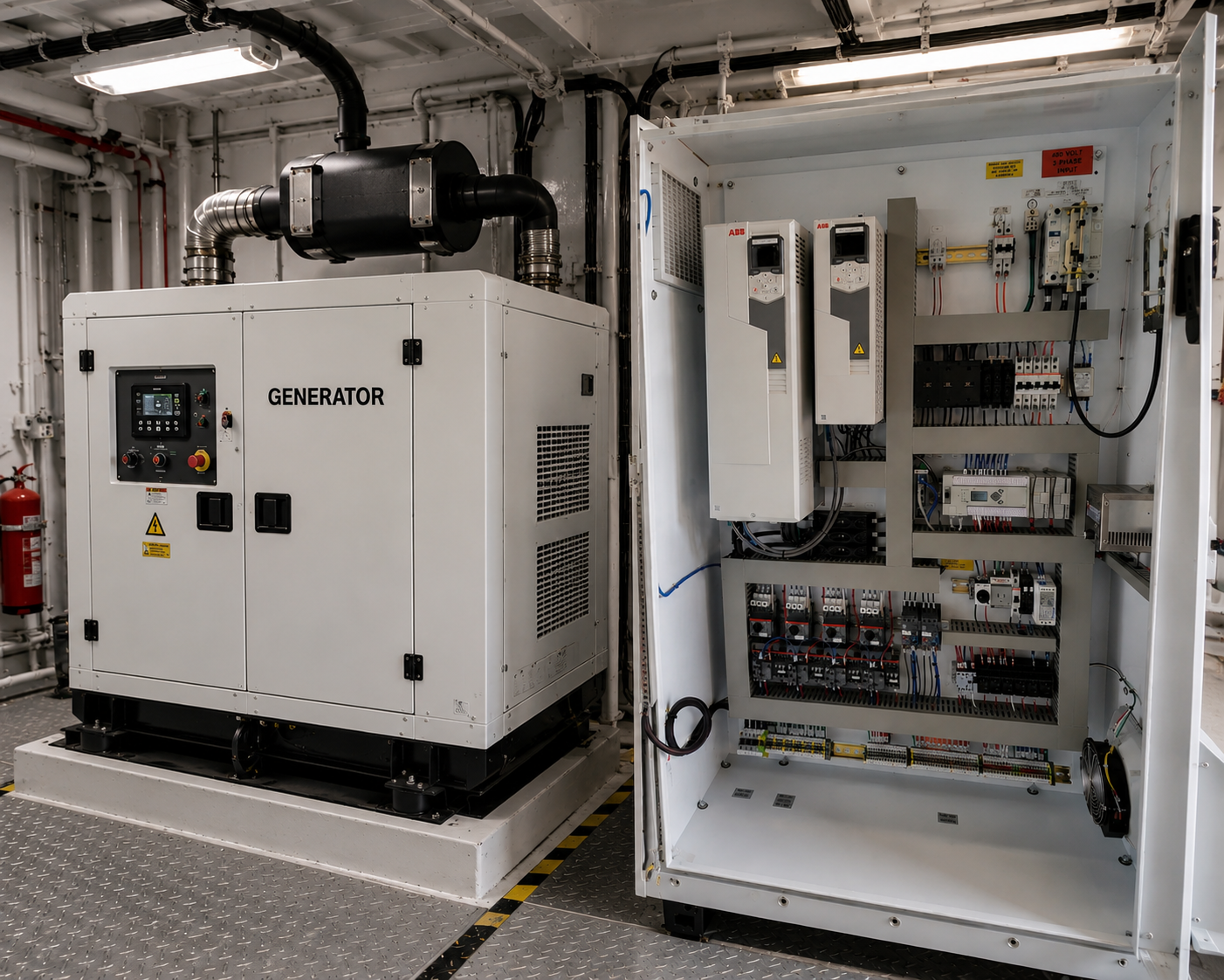
In a marine generator application, the VFD allows the prime mover (diesel engine or gas turbine) to operate at precisely the speed required to meet real-time electrical demand rather than running at a fixed 1,200 or 1,800 RPM regardless of load. This fundamental change in how power is generated and distributed transforms the economics of vessel operation.
A VFD system integration replaces inefficient fixed-speed operation with intelligent speed control.
Instead of restricting flow mechanically, Variable Frequency Drives:
By matching output to operational requirements, VFD retrofit delivers immediate and measurable energy savings.
The process begins with a technical review of the vessel’s auxiliary systems, with emphasis on generators operating under variable load conditions.
This stage includes:
The objective is to define where variable speed operation can deliver measurable efficiency gains.
Comprehensive power quality and energy consumption analysis for your vessel. GLO Marine's onboard energy audits identify inefficiencies, quantify potential savings, and provide a detailed ROI model for VFD investment.
Custom VFD system design for marine generator applications. Our certified marine electrical engineers analyze your vessel's power profile, load curves, and operational profile to specify the optimal drive configuration for maximum savings and reliability.
This includes:
All designs are prepared to ensure safe, compliant, and reliable operation.
Installation is performed in accordance with the approved engineering design and is planned to align with the vessel's operational constraints. The scope may vary depending on system complexity, but typically includes electrical works and control system integration.
Activities generally involve:
Full VFD installation aboard vessels at sea, in port, or in drydock. Our teams are mobilized globally within 48 hours. All commissioning performed to class society standards with full documentation package for your vessel's classification record.
The system is commissioned to verify functionality and performance under real operating conditions. This ensures that all components operate as intended and that the expected efficiency improvements are achieved.
This phase includes:
Where required, post-commissioning support can be provided to monitor performance and confirm long-term energy savings.
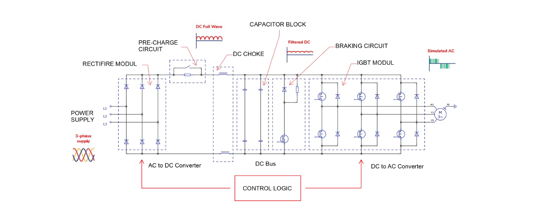
The VFD converts fixed frequency shipboard power into a variable frequency output through:
• Rectifier section converting AC to DC: Utilizes a 6-pulse or 12-pulse diode bridge (or Active Front End - AFE for low harmonics) to convert incoming three-phase AC voltage into a pulsating DC voltage.
• DC link with smoothing components: Features a high-capacity capacitor bank and DC chokes to filter voltage ripples, provide energy storage for load transients, and decouple the rectifier from the inverter.
• Inverter section generating controlled AC output: Employs high-speed Insulated Gate Bipolar Transistors (IGBTs) using Pulse Width Modulation (PWM) to reconstruct a variable frequency and voltage AC waveform for the motor.
• Internal protection and control electronics: Integrated microprocessors monitor real-time parameters such as overcurrent, overvoltage, thermal overload, and earth faults, ensuring millisecond-level response times.
Drives are selected based on:
• Motor rating and starting current
• Voltage level and supply characteristics
• Ambient engine room conditions
• Harmonics limits of the vessel's electrical network
• Class approval requirements
The existing motor is typically retained, provided insulation class and thermal capacity are suitable for inverter operation.
Assessment includes:
• Motor insulation rating: Verification of insulation class (Class F/H) against high voltage gradients. We ensure windings can withstand PWM-induced stress without premature dielectric breakdown.
• Bearing condition and suitability for inverter duty: Mitigation of common-mode voltages and shaft currents (EDM discharges). We evaluate the need for insulated bearings or shaft grounding rings to prevent failure due to surface corrosion and grooving.
• Cooling method: Analysis of cooling efficiency at low speeds.
• Cable length and shielding requirements: Assessment of cable length, impedance matching, and shielding requirements to minimize Electromagnetic Interference (EMI) and reflected wave phenomena.
Where necessary, output filters may be applied to manage voltage rise time and protect motor windings.
The VFD can operate under several control modes:
• Pressure control for cooling pumps: Maintains a constant differential pressure across the cooling system, regardless of flow demand. Pressure transducers provide real-time feedback to the VFD’s internal PID controller.
• Temperature control for central cooling circuits: Dynamically adjusts the speed of seawater pumps based on the HT/LT fresh water temperature. This method maximizes fuel savings, especially when operating in colder waters.
• Flow control: Applied where flow measurement is available, ensuring precise fluid circulation according to process requirements while eliminating throttling losses.
• Fixed speed override for contingency: A critical safety feature (Contingency Mode) that allows the motor to run at a predefined bypass speed in the event of sensor failure or operator intervention.
The drive receives feedback from existing or added sensors and adjusts speed to maintain the defined setpoint.
Control can be:
• Standalone local loop
• Integrated into the vessel automation system
• Interfaced with group starter logic
The objective is to maintain stable operation while reducing unnecessary power consumption.
Our electrical engineering team designs VFD Integration to minimise disruption to existing systems.
Key considerations include:
• Interface with existing starters and protection devices: We interface the VFD with existing motor starters (DOL/Star-Delta), utilizing current power circuits. Protection devices, such as circuit breakers and ultra-fast fuses, are precisely recalibrated to match the inverter’s load characteristics.
• Retention of start, stop, and alarm philosophy: The vessel’s original "Start/Stop" philosophy and alarm management remain intact. This ensures a zero-learning curve for the crew, as the VFD manages complex motor ramps and speed control behind the scenes.
• Power supply capacity and short circuit level: We evaluate the main busbar capacity and short-circuit levels (kA). The system is designed to withstand grid transients and maintain proper protection selectivity across the electrical distribution network.
• Bypass configuration where required: For mission-critical applications, we implement manual or automatic bypass systems. This allows the motor to revert to Direct-On-Line (DOL) operation during VFD maintenance, ensuring 100% uptime.
Harmonic analysis may be required depending on vessel network characteristics and drive size.
Depending on vessel redundancy philosophy and classification society requirements, a bypass arrangement may be implemented.
Options include:
• Manual bypass switch: A robust and cost-effective solution featuring a mechanically interlocked selector switch. It allows for an easy transfer from VFD control to Direct-On-Line (DOL) operation, enabling scheduled maintenance without process interruption.
• Automatic bypass in case of drive fault: An intelligent monitoring system that detects VFD faults in real-time and automatically triggers a switchover to grid power. This configuration is essential for mission-critical applications where downtime is not an option.
• Redundant pump or fan configuration without bypass: For systems with existing Duty/Standby units, we can implement a logic-based redundancy. In the event of a VFD failure, the automation system immediately activates the secondary redundant unit, maintaining system parameters without the need for a dedicated bypass on each drive.
The solution is defined during engineering to ensure operational continuity and compliance.
Most vessels can benefit from a marine VFD retrofit, especially those with:
A technical assessment is required to evaluate feasibility and expected savings.
Marine generator VFD solutions are suitable for a wide range of vessel types and operational profiles, including: Offshore support vessels, Tankers, Bulk carriers, Container vessels, Passenger vessels, Dredgers, Research vessels, Offshore construction vessels.
A typical marine VFD retrofit includes:
All work must comply with class and marine standards.
In most cases, a VFD retrofit can be implemented with minimal disruption. Systems are integrated into existing electrical infrastructure, although some modifications to control systems, cabling, or switchboards may be required.
Return on investment typically ranges from 6 months to 2 years, depending on fuel costs, operating hours, and system size. High-use systems often achieve faster payback due to significant energy savings.
By reducing electrical demand and fuel consumption, a marine VFD retrofit directly lowers CO₂ emissions. It is considered one of the most practical and low-risk solutions in a vessel decarbonisation strategy.
Yes, marine VFD systems must comply with classification society rules (such as DNV, ABS, Lloyd’s Register). Retrofit projects include proper documentation, approvals, and testing to ensure compliance.
Installation is typically planned during dry dock or scheduled maintenance periods; however, in some cases, phased installation can be carried out during operation with proper planning.
Planning a marine generator upgrade or evaluating VFD integration opportunities onboard your vessel?
Our specialists can assess your electrical systems, identify efficiency opportunities, and develop a structured retrofit approach tailored to your operational profile.


